Esp8266 Applemidi Mcp4728 Midi2cv
What is Esp8266 Applemidi Mcp4728 Midi2cv
ESP8266_AppleMIDI_MCP4728_MIDI2CV is a project that converts MIDI messages into control voltage using the AppleMIDI protocol, implemented on an ESP8266 microcontroller with two MCP4728 DACs.
Use cases
Use cases include sending control voltage from a DAW to hardware synthesizers, creating hybrid setups for live performances, and facilitating MIDI control in modular synth environments.
How to use
To use ESP8266_AppleMIDI_MCP4728_MIDI2CV, change the STASSID and STAPSK in the code to match your WiFi settings. The ESP8266 will then connect to your network and function as an Access Point, allowing devices like PCs or iPads to send MIDI messages directly.
Key features
Key features include the ability to convert MIDI messages to control voltage, support for multiple outputs (up to 8 with two MCP4728s), and the capability to send triggers. It operates with low latency by connecting devices directly to the ESP8266.
Where to use
This project is suitable for music production environments, particularly for users of digital audio workstations (DAWs) like VCV Rack or miRack, who want to integrate virtual control voltage with real synthesizers.
Clients Supporting MCP
The following are the main client software that supports the Model Context Protocol. Click the link to visit the official website for more information.


Overview
What is Esp8266 Applemidi Mcp4728 Midi2cv
ESP8266_AppleMIDI_MCP4728_MIDI2CV is a project that converts MIDI messages into control voltage using the AppleMIDI protocol, implemented on an ESP8266 microcontroller with two MCP4728 DACs.
Use cases
Use cases include sending control voltage from a DAW to hardware synthesizers, creating hybrid setups for live performances, and facilitating MIDI control in modular synth environments.
How to use
To use ESP8266_AppleMIDI_MCP4728_MIDI2CV, change the STASSID and STAPSK in the code to match your WiFi settings. The ESP8266 will then connect to your network and function as an Access Point, allowing devices like PCs or iPads to send MIDI messages directly.
Key features
Key features include the ability to convert MIDI messages to control voltage, support for multiple outputs (up to 8 with two MCP4728s), and the capability to send triggers. It operates with low latency by connecting devices directly to the ESP8266.
Where to use
This project is suitable for music production environments, particularly for users of digital audio workstations (DAWs) like VCV Rack or miRack, who want to integrate virtual control voltage with real synthesizers.
Clients Supporting MCP
The following are the main client software that supports the Model Context Protocol. Click the link to visit the official website for more information.
Content
MIDI to CV (ESP8266, MCP4728, AppleMIDI Library)
In this project I convert MIDI messages to control voltage and triggers via the AppleMIDI using an ESP8266 and two MCP4728.
Change the STASSID and STAPSK to match your WiFi network settings. The ESP8266 connects to your network and will show up as an Access Point with the postfix “extender”. So for example if your network name is “mywifinetwork”, the ESP8266 will show up as “mywifinetworkextender”
Goals
I use VCV Rack as my DAW and I wanted to have a hybrid setup where I would be able to send “virtual” control voltage to my real synthesizers. In my case from VCV Rack on my PC (https://vcvrack.com/) or miRack (https://mirack.app/) on my iPad to my AEmodular synth from https://www.tangiblewaves.com/.
Having 4 output jacks is good. But I thought it would be better to have 8. So I wanted to use two MCP4728. I also wanted to be able to send triggers. For now I use 4 output PINs from the ESP8266.
I am not good at soldering and I don’t have experience designing electrical circuits. So I decided to use a programmable microcontroller (in this case the ESP8266) using Arduino libraries. I just had to combine the examples from two libraries (see details below). I plugged everything together on a breadboard.
Code from the AppleMIDI-Library example
To keep the latency low, I wanted to connect my PC or iPad directly to the ESP8266. My code is based on this example from the AppleMIDI-Library:
https://github.com/lathoub/Arduino-AppleMIDI-Library/blob/master/examples/ESP8266_NoteOnOffEverySec_softAP_mDNS/ESP8266_NoteOnOffEverySec_softAP_mDNS.ino
This code shows how to set up an Access Point on the ESP8266 so that my PC or iPad can connect to the ESP8266.
Code from the ESP8266 WiFi examples (Range Extender)
When you use the example above, your PC or iPad is not connected to the internet anymore. I used this example from the ESP8266 WiFi examples to set up an Access Point which forwards the traffic to the internet:
https://github.com/esp8266/Arduino/blob/master/libraries/ESP8266WiFi/examples/RangeExtender-NAPT/RangeExtender-NAPT.ino
Note: you should not download a lot of data while using the MIDI module because this increases the latency. And the bandwidth is very limited. So your downloads will be slower. But it is better than being disconnected from the internet completely.
Changing the device ID of the MCP4728
The MCP4728 boards all have the same ID. But you can change the ID so that you can use more that one board. It was a bit tricky but in the end it worked for me. I used the code from this project:
https://github.com/TrippyLighting/HPRGB2/blob/master/examples/changeDeviceID/changeDeviceID.ino
See also
https://forum.arduino.cc/t/mcp4728-x2-with-and-without-multiplexer-tc9548a-resolved/983859
This i2c-scanner.ino Github Gist helped me finding the IDs
https://gist.github.com/netmaniac/8706f2f7ae5dbfe6498e04bf1cbfde4a
How it works
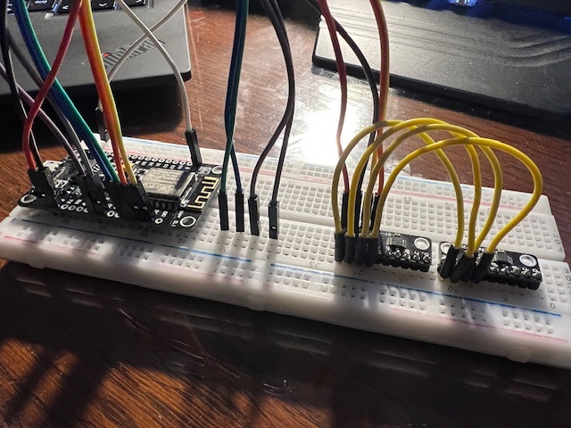
This section describes how all the components work together and how they are connected.
Connections
- The ESP8266 is powered via the USB input (plugged into a computer or a power bank)
- D1 of the ESP8266 into the CL input of the MCP4728 (long yellow cable)
- D2 of the ESP8266 into the DA input of the MCP4728 (orange cable)
- Ground from the ESP8266 into the G input of the MCP4728 (black cable)
- 3V from the ESP8266 into the V input of the MCP4728 (red cable)
- Also: connect the respective inputs of the two MCP4728 boards (short yellow cables)
- The trigger output PINs are D3, D4, D5 and D6 (green, blue, grey, purple cable)
VCV Rack Modules
- CV->MIDI CC module https://vcvrack.com/manual/Core#CV-CC
- Gate->MIDI module https://vcvrack.com/manual/Core#CV-Gate
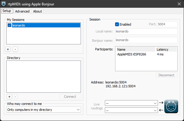
rtpMIDI Software
I use Tobias Erichsens rtpMIDI software and it works great for me
https://www.tobias-erichsen.de/software/rtpmidi.html
Why didn’t you use …?
MIDI via Bluetooth
I didn’t use MIDI via bluetooth for two reasons.
It was difficult to set up on Windows. I tried BLE-MIDI Connect (https://apps.microsoft.com/detail/9nvmlzttwwvl) and MIDIberry (https://apps.microsoft.com/detail/9n39720h2m05). It worked somehow but not as smooth as I hoped.
But mainly I didn’t use a BLE-MIDI library (for example https://github.com/max22-/ESP32-BLE-MIDI) for this project because I have an old iPad where the MIDI via Bluetooth connection didn’t work. I have a project where I use an ESP32 with the BLE-MIDI library (https://github.com/duddex/ESP32-BLEMIDI2CV). But this only works with my new iPad.
ESP32
This will be my next project.
Findings / Know issues / Limitations
- The max output voltage from the MCP4728 modules in this setup is only 3.3v
- Using the VCV Rack “CV->MIDI CC” module 0v is MIDI value 0 and 10v is MIDI value 127
- Negative VCV Rack voltages result in MIDI value 0
- Use (for example) the OFFSET module from Bogaudio (https://library.vcvrack.com/Bogaudio/Bogaudio-Offset) to make sure that the voltage is in the correct range from 0v to 10v
- D2 is also internal LED
- If D2 is low, the LED is on
- IF D2 in high, the LED is on
- It is possible that the trigger output is too short
- You can use the DGate module from Bogaudio (https://library.vcvrack.com/Bogaudio/Bogaudio-DGate) to extend the trigger length. See example below
- Higher latency when debug output is enabled
- Remove the
DBG(F("ControlChange")line insetHandleControlChangeif you the latency gets too high
- Remove the
Examples
Sloth
In this example I use the Sloth Apacy module from Nonlinear Circuits (https://library.vcvrack.com/NonlinearCircuits/SlothApathy).
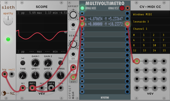
The value for offset in the OFFSET module is set to 5v so that the output voltage is between 0v and 10v (actually 10.23372v in my screenshot).
The MULTIVOLTIMETRO module is just used for testing. It is not necessary to include the module in a patch.
The output of the OFFSET module is patched into the CV->MIDI CC module and the CC messages are sent to MIDI channel 1 on CC channel 0. On my PC I have connected rtpMIDI to my ESP8266. My computer’s name is leonardo. So this is the name that shows up in the CV->MIDI CC module as the name of the MIDI device.
DGate
When you send triggers which are very short (as triggers usually are because they are triggers) the NoteOn and NoteOff messages are sent almost at the same time. This could lead to dropouts.
You can use the DGate module from Bogaudio (https://library.vcvrack.com/Bogaudio/Bogaudio-DGate) to extend the trigger length.
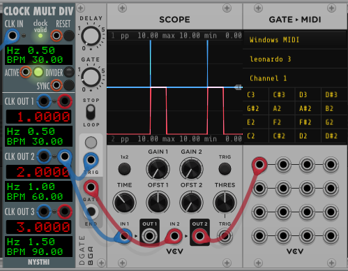
In this picture you see the trigger as a blue line and the “extended” trigger (gate) as red line. Here I set the gate length to 0.2 seconds.
Dev Tools Supporting MCP
The following are the main code editors that support the Model Context Protocol. Click the link to visit the official website for more information.